I’ve researched this rather a lot and to date all of the examples, tutorials and so forth at all times use the next order: Scale * Rotate * Translate however for some motive this order should at all times be backwards in my Scene Graph. I’m not positive if that is meant attributable to reworking native matrix to world matrix or it’s an inherent bug in my utility.
Right here is my easy Scene Graph implementation. I’m utilizing Vulkan and GLM math library.
void SceneNode::setTransform(glm::mat4 remodel) {
  transformLocal = remodel;
}

void SceneNode::replace() {
  // if root node
  if (parentNode == nullptr) {
    transformWorld = transformLocal;
  } else {
    transformWorld = parent->transformWorld * transformLocal;
  }

  for (auto &node : youngsters) {
    node->replace();
  }
}
And my shader logic:
// initialization code hidden for simplicity

void fundamental() {
  // worldTransform = remodel matrix calculated throughout scene node replace
  gl_Position = UniformCameraData.projectionView * ModelPushConstants.worldTransform * vec4(vPosition, 1.0f);

  outColor = vColor;
}
As a demo, I’ve created an excellent easy scene with spheres:
Root
  Sphere Middle -> Rotate round its personal axis
    Sphere 1 -> Place someplace close to the father or mother and Rotate round its personal axis
    Sphere 2 -> Place someplace close to the father or mother andRotate round its personal axis
    Sphere 2 -> Place someplace close to the father or mother andRotate round its personal axis
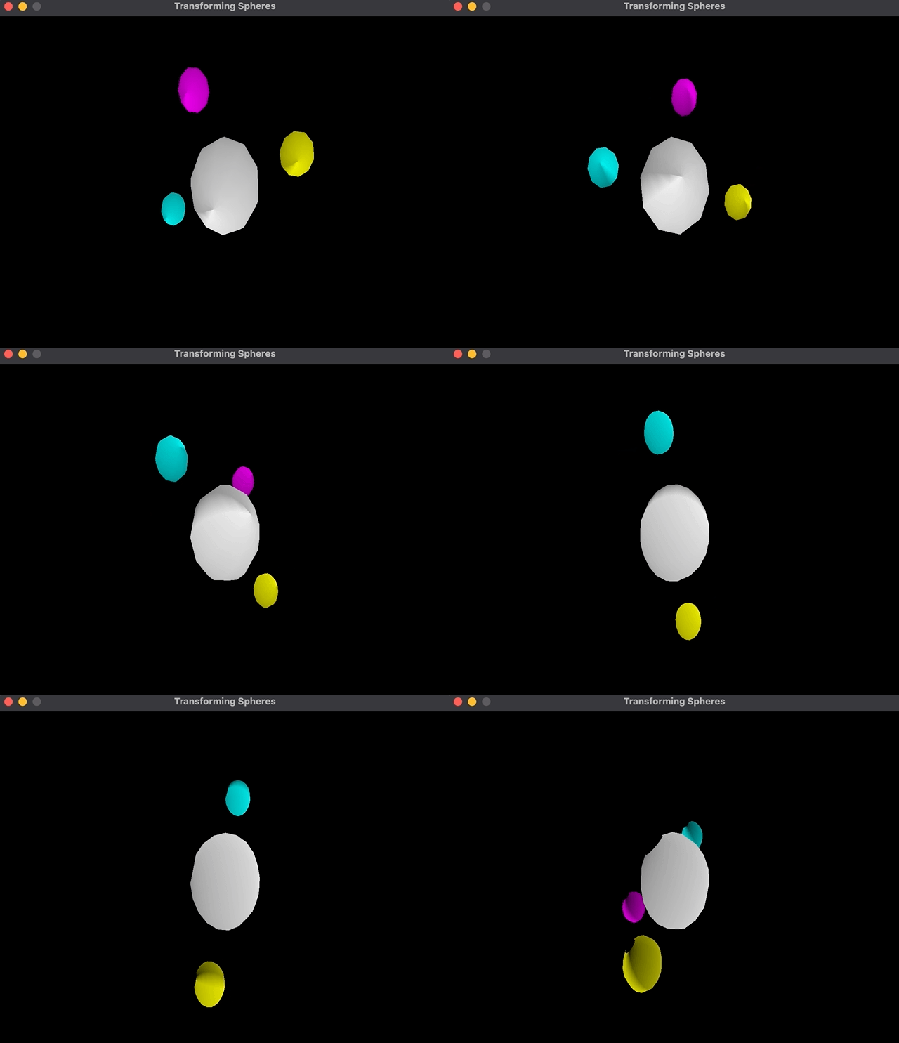
This scene graph provides me one sphere within the center that rotates and three spheres that rotate attributable to being youngsters of this sphere; plus, the spheres themselves rotate round their very own axis:
Nevertheless, the implementation of it’s quiet bizarre to me. The order of transformations is Translate * Rotate * Scale as a substitute of the opposite means round:
child1->setTransform(
          glm::translate(glm::mat4{1.0}, glm::vec3{2.0, 0.0, 0.0}) *
          glm::rotate(glm::mat4{1.0f}, glm::radians(body * 0.9f),
                      glm::vec3{0.0, 0.0, -1.0}) *
          glm::scale(glm::mat4{1.0}, glm::vec3{0.4, 0.4, 0.4}));

// ...different youngsters transformations

scene->replace();
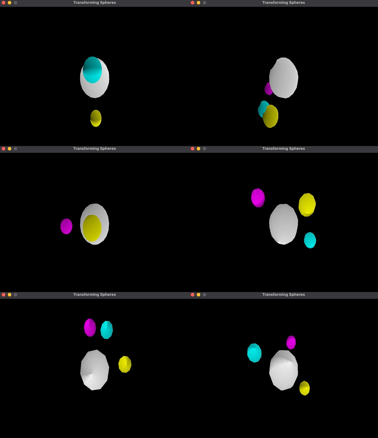
After I change the order of transformations, the rotation occurs across the central sphere:
child1->setTransform(
          glm::rotate(glm::mat4{1.0f}, glm::radians(body * 0.9f),
                      glm::vec3{0.0, 0.0, -1.0}) *
          glm::translate(glm::mat4{1.0}, glm::vec3{2.0, 0.0, 0.0}) *
          glm::scale(glm::mat4{1.0}, glm::vec3{0.4, 0.4, 0.4}));

// ...different youngsters transformations

scene->replace();
As you may see, the cyan coloration sphere rotates across the father or mother as a substitute of its personal middle.
I used to be confused by this so, I added translation to the basis node (e.g (2.0, 1.0)) and acquired the identical end result. If I rotate the sphere, then translate, it should rotate towards (0, 0), then translate to (2.0, 1.0) on the similar time, which is able to imply that it’s at (2.0, 1.0) and rotating towards (0.0, 0.0). Then again, if I translate first, then rotate, it should rotate towards (2.0, 1.0) and translate to (2.0, 1.0) on the similar time, which is able to imply that its rotating towards the newly translated middle.
Logically this is sensible to me as a result of these multiplications are taking place on the similar time and the result’s written to node however I nonetheless don’t perceive why the sometimes recommended transformation order is Scale * Rotate * Translate. Can somebody clarify to me what I’m lacking right here that I’ve to make use of multiply transformations is in reverse order?


